Why Camshaft Grinding Is Not Just Round-Part Grinding
A crankpin is round. A cam lobe is not. It is a precisely shaped profile — base circle, ramp, flank, nose — that opens the engine valve at the right time for the right duration. To grind a cam, the wheel has to follow the lobe shape while the camshaft rotates, and the relative angle between lobes on the same shaft has to be exact.
Done right, the cam profile holds to within 0.005 mm of the design shape, surface finish under Ra 0.2 μm, and the lobe-to-lobe phase angle is accurate to within 0.05° across a 5-lobe shaft. Done wrong, the engine runs rough, the valves open at the wrong time, and the cam wears out fast.
This guide covers how the machine works, the two main configurations (master-cam copy and CNC profile), and what to check when buying. For the comparable crankshaft process, see Crankshaft Grinder: Working Principle, Types, and Buying Guide.
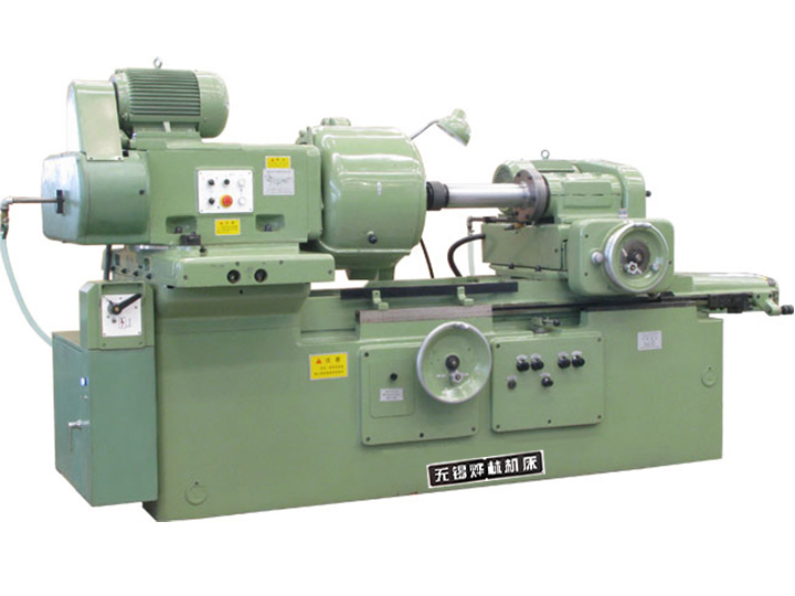
How a Camshaft Grinder Works
The camshaft is clamped between two workheads and rotated slowly. The grinding wheel is mounted on a workhead that can move radially as the cam turns — it has to follow the cam profile. The wheelhead itself does not move axially (one lobe at a time). After each lobe is ground, the workhead indexes to the next lobe by rotating the shaft to the next angular position.
Three motions drive the process:
Wheel rotation at 30–45 m/s. Camshaft wheels are smaller than crankshaft wheels (typically 300–500 mm) to allow the lobe profile to fit.
Workpiece rotation at slow RPM, set so the lobe surface speed is in the 15–30 m/min range.
Wheel infeed (radial) as the cam profile develops. This is the unique motion: the wheelhead follows the cam contour, not a straight cylindrical path.
Between lobes, the workhead rotates the shaft to the next angular position with high accuracy — typically within 0.02°. Cumulative error across a 5-lobe shaft has to stay under 0.1° for the cam timing to be correct.
Master-Cam Copy Grinding
The traditional method, still widely used in 2026:
A master cam — a hardened steel cam with the exact profile to be ground — is attached to the camshaft axis on a separate spindle.
A cam roller follower rides on the master cam as the camshaft rotates.
The roller follower is mechanically linked to the grinding wheel infeed.
As the camshaft turns, the master cam lifts the follower, the follower pushes the wheel inward, and the lobe shape is generated as a 1:1 mechanical copy.
Advantages:
Fast. Cycle time per lobe is 5–15 seconds on a well-set machine.
No programming. The master cam is the program. Change the part, change the master cam.
Proven. The technology has been in production for 70+ years and still works.
Disadvantages:
Master cams are expensive. Each lobe design requires a precision-ground master cam. Five different lobe profiles in a cam family = five master cams.
Not flexible. Changing the lobe design requires a new master cam. Design changes during a production run are slow.
Profile correction is hard. If the lobe is wrong, the master cam has to be re-cut or re-ground.
Master-cam copy grinders are still the right answer for high-volume production of a fixed cam design — aftermarket replacement camshafts, motorcycle camshafts, and OEM camshafts on stable engine families.
CNC Profile Grinding
The modern method, dominant in new OEM lines since 2015:
The lobe profile is encoded as a mathematical curve (typically expressed in degrees of rotation vs lift in mm).
The CNC controller commands the wheel infeed axis (C axis or X axis) to follow that curve as the camshaft rotates.
The wheel grinds the lobe with no mechanical master — the profile comes from the program.
After each lobe, the controller indexes to the next lobe with sub-degree accuracy.
Advantages:
No master cam needed. Profile changes are made in software. A new lobe design is a 30-minute setup vs a 2-week master-cam build.
Profile correction is easy. Iterating on the lobe shape is a matter of editing the curve. Useful for prototype engines and motorsport.
Lobe-to-lobe phase accuracy. The indexing is repeatable within 0.01° across the entire shaft. Master-cam grinders are typically 0.05°.
Data logging. Every lobe profile is measured, recorded, and traceable. Required for aerospace and motorsport certifications.
Disadvantages:
Slower cycle time. 15–30 seconds per lobe on a CNC grinder vs 5–15 seconds on a master-cam machine.
Higher capital cost. A CNC camshaft grinder is 1.5–2× the price of a master-cam machine.
Programming skill required. Operators need to understand cam design and CAM software.
CNC profile grinders are the right answer for any shop that runs more than one or two cam designs, or where the design is still changing. Most OEM lines, motorsport shops, and aerospace valve-train suppliers have moved to CNC.
Tolerances That a Good Camshaft Grinder Holds
Numbers below are typical for a
CNC camshaft grinder on automotive camshafts. Motorsport, aerospace, and large diesel engines tighten these.
|
Parameter |
Typical tolerance |
|
Lobe profile accuracy |
±0.005 mm vs design curve |
|
Base circle diameter |
±0.005 mm |
|
Lobe surface finish |
Ra 0.2–0.4 μm |
|
Lobe-to-lobe phase angle |
±0.05° (CNC); ±0.10° (master-cam) |
|
Lift at TDC (top dead center) |
±0.005 mm |
|
Lobe roundness on circular flank |
0.002 mm |
|
Journal roundness |
0.002 mm |
|
Journal-to-lobe concentricity |
±0.01 mm |
For high-performance engines (motorsport, high-power diesel), the lobe profile accuracy drops below 0.003 mm and surface finish drops below Ra 0.2 μm. That requires a high-rigidity CNC grinder with profile compensation based on in-process measurement.
Wheel Selection for Camshaft Grinding
Camshaft wheels are smaller than crankshaft wheels and run at higher RPM. The profile is what decides the wheel shape. Common specs:
Grit: 60–80 for roughing on forged steel camshafts; 100–120 for finishing.
Grade: J–K for soft steels (below 250 HB); L–N for chilled cast iron or hardened (above 55 HRC).
Bond: Vitrified for general use; resin for high-stock-roughing.
Wheel diameter: 300–500 mm typical. Smaller wheels allow tighter profile radii.
Dressing: CNC profile dressing with a diamond roll is standard on CNC machines. Master-cam machines use a fixed single-point dresser.
For chilled-cast-iron camshafts (common in heavy-duty diesel), use a softer grade to prevent burn. Dress more often — chilled cast iron loads the wheel faster than forged steel.
Common Defects and How to Diagnose Them
Profile error on the flank. Cause: master cam wear, or wheel-head backlash on a CNC machine. Fix: replace master cam; check CNC backlash compensation.
Lobe-to-lobe phase drift. Cause: indexing pin wear, workhead bearing wear, or backlash in the index drive. Fix: replace indexing pin; check workhead bearing preload; re-shim index drive.
Surface burn (temper colors). Cause: insufficient coolant at the contact zone, or wheel loading. Fix: open coolant nozzle, dress more often, switch to softer grade.
Out-of-round base circle. Cause: workhead runout, or wheel spindle bearing wear. Fix: check workhead runout (under 0.002 mm); check wheel spindle bearing preload.
Wrong lift at TDC. Cause: angular reference error between the controller and the camshaft. Fix: re-master the encoder; check coupling backlash.
Master-Cam vs CNC: When to Buy Which
The decision is mostly about how many cam designs you run and how often they change.
Master-cam. Right for high-volume aftermarket production of one or two fixed cam designs, where the master cam is a sunk cost that pays back over years of production.
CNC. Right for OEM production with frequent design changes, for prototype engines, and for shops grinding 5+ cam designs per year. Also right for aerospace and motorsport where data logging is required.
Capital cost: master-cam machines start around US $120K FOB Wuxi; CNC camshaft grinders start around $250K and run to $800K for OEM production with automation. Most buyers in the middle (aftermarket with 3–4 cam designs) choose CNC.
Modern Trends in 2026
Inline measurement. Camshaft profile is measured in-process with a touch probe; the controller adjusts the infeed on the next lobe to compensate for wear. Standard on high-end CNC machines.
Adaptive grinding. The controller adjusts wheel speed and coolant flow based on the lobe shape and material being cut. Improves wheel life by 20–40%.
Multi-profile wheels. One wheel carries two or three profiles. The wheelhead shifts radially to switch profiles, cutting wheel-change time. Common on small-engine camshafts.
Dry grinding for select materials. Some cast-iron cam profiles can be ground dry with CBN wheels, eliminating coolant. The cycle time drops by 10–20%. Still niche in 2026.
Integrated polishing. A separate polishing station built into the grinder, using a fine-grit belt or a felt wheel. Replaces a separate polishing machine for some OEMs.
Camshaft Grinder Specifications Buyers Should Check
Max workpiece length and weight. Same rule as crankshaft: size with margin. A 4-cylinder engine cam is typically 400–500 mm; a V8 cam can hit 700 mm.
Max journal diameter. Standard machines cover 30–80 mm. Heavy-duty large-engine cams go to 150 mm.
Indexing accuracy. Look for under 0.02° between lobes. Cumulative accuracy across the shaft has to stay under 0.1°.
Profile servo bandwidth. The X-axis (wheel infeed) has to follow the cam profile at 60–120 Hz minimum. Below that, the profile roundness suffers.
Wheelhead power. 5.5 kW on small cams, 11+ kW on heavy-stock cams.
Coolant flow. Cams generate less heat than crankshafts per pin, but the contact zone is smaller. 20–40 L/min at the wheel.
FAQ
Q: What is the difference between a camshaft grinder and a crankshaft grinder?
A: A crankshaft grinder indexes between round pins. A camshaft grinder follows a non-round lobe profile on every pin. The workhead on a camshaft grinder has to follow the cam contour, not just rotate to a fixed angle. See Crankshaft Grinder for the crankshaft side.
Q: What is a master cam?
A: A precision-ground steel cam that is mounted on the camshaft axis on a copy grinder. A roller follower rides on the master cam and mechanically drives the wheelhead. The master cam defines the lobe profile. Each cam design requires its own master cam.
Q: How much does a camshaft grinder cost?
A: Indicative FOB Wuxi in 2026: master-cam copy grinder, US $120K–$300K for small to mid-size; CNC camshaft grinder, US $250K–$800K. Add automation and in-process measurement for OEM production.
Q: What tolerances can a CNC camshaft grinder hold?
A: Lobe profile accuracy ±0.005 mm vs design curve, base circle diameter ±0.005 mm, surface finish Ra 0.2–0.4 μm, lobe-to-lobe phase ±0.05°. Master-cam machines are typically 2× those tolerances.
Q: How long does it take to grind one camshaft?
A: Master-cam machine: 2–4 minutes per shaft (4-cylinder). CNC machine: 5–8 minutes per shaft. The CNC is slower per lobe but more flexible across designs.
Q: Can a CNC camshaft grinder replace a master-cam machine in production?
A: Yes, on most parts. The CNC is slower per lobe (15–30 seconds vs 5–15 seconds on a master-cam machine), but the absence of master cams and the flexibility to change lobe designs outweigh the per-lobe penalty on most production lines.
Q: What is the typical wheel life on a camshaft grinder?
A: 50–150 shafts per wheel on forged steel, 200+ shafts per wheel on chilled cast iron, depending on stock removal and dressing discipline. CNC grinders with auto-dress extend wheel life by 20–30%.
Q: Is CNC profile grinding suitable for aftermarket parts?
A: Yes, increasingly so. Aftermarket camshaft suppliers with 5+ SKUs prefer CNC because the master-cam cost is amortized over many designs. For a single high-volume SKU, master-cam is still cheaper.
Bottom Line
A camshaft grinder profiles non-round cam lobes with sub-degree phase accuracy and micron-level profile tolerance. The two configurations — master-cam copy and CNC profile — serve different production needs: master-cam for stable, high-volume designs, CNC for flexibility and changing designs.
Yelin's camshaft grinder line covers both segments, from the small master-cam copy machines used in motorcycle and small-engine aftermarket production to the CNC profile grinders used in OEM automotive and diesel lines. If you are sizing a camshaft grinder, send us the cam design (or a print), the journal-to-lobe layout, weekly output, and tolerance requirements. We will respond with a recommended configuration and indicative price. See the full Yelin grinder product line or contact our engineering team.
 English