1. Introduction
As the heart of internal combustion engines, crankshafts convert piston reciprocating motion into rotational motion, directly affecting engine performance. After rough machining, precision grinding is essential to eliminate deformation and improve journal accuracy. Crankshaft grinders, with unique follow-up grinding and multi-axis synchronization, achieve high precision (roundness ≤ 0.001 mm, Ra ≤ 0.04 μm), meeting the stricter requirements of advanced engine technology.
2. Structural Composition and Working Principle
2.1 Core Structural Components
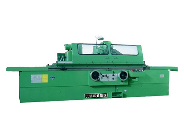
- Machine Base: Made of high-quality cast iron or Granitan® with vibration-damping systems, ensuring rigidity and thermal stability for long-term operation.
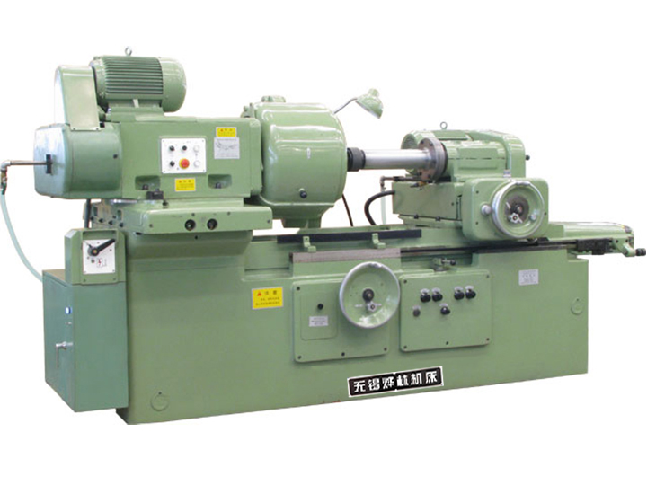
- Spindle System: Consists of workpiece and grinding spindles, with high-precision bearings to control runout within 0.001 mm, enabling stepless speed regulation.
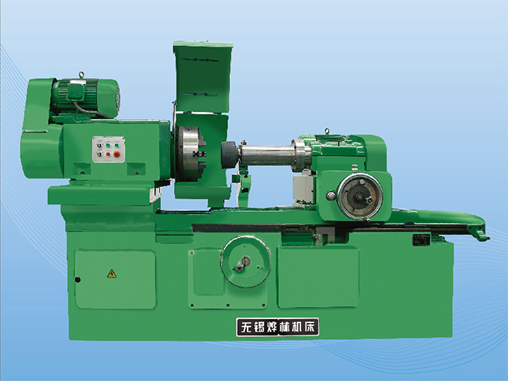
- Grinding Wheel and Dressing System: CBN/diamond superabrasive wheels, with automatic diamond roller dressing to maintain sharpness and profile accuracy.
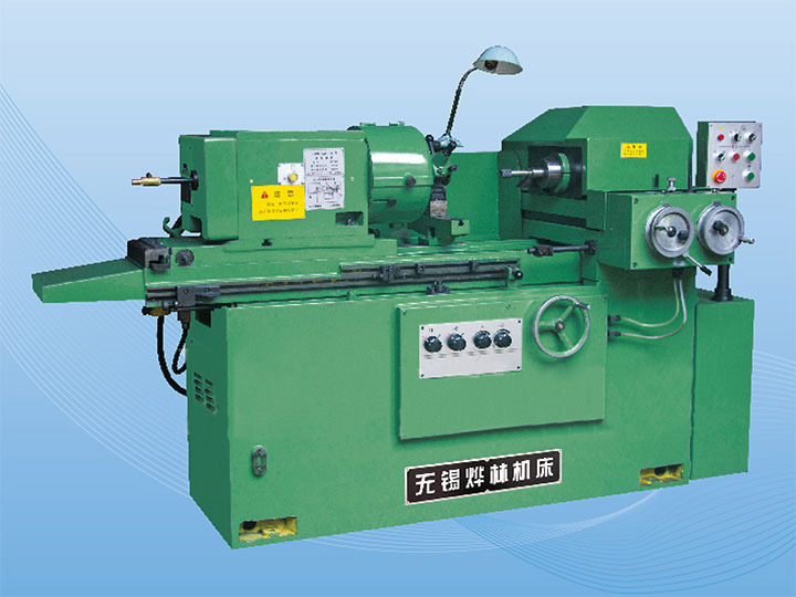
- Feed and Control Systems: Precision servo-driven feed (accuracy ≤ 0.0005 mm) and advanced CNC systems (Siemens/Fanuc) with automatic compensation and detection functions.
- Cooling, Clamping and Detection Systems: High-pressure filtered cooling, center frame clamping, and online detection for real-time quality control.
2.2 Working Principle
Crankshaft grinders use two main methods: plunge grinding (for main journals, high-efficiency mass production) and follow-up grinding (for rod journals, one-time clamping, high precision). The composite motion of crankshaft rotation and grinding wheel movement forms a high-quality surface, with key parameters (speed, feed, pressure) directly affecting processing quality.
3. Classification and Technical Characteristics
3.1 Classification
- By Grinding Method: Plunge grinding (main journals) and follow-up grinding (high-precision rod journals).
- By Structure: Horizontal (mainstream, long crankshafts) and vertical (small/medium crankshafts).
- By Control: Manual (small-batch repair), semi-automatic, and full-CNC (large-batch high-precision production).
- By Scale: Small (passenger vehicles), medium (commercial vehicles), and heavy-duty (marine/aerospace).
3.2 Core Technical Characteristics
- High Precision: Roundness ≤ 0.001 mm, Ra ≤ 0.04 μm, dimensional accuracy ±0.001 mm.
- Strong Adaptability: Processes various crankshaft types and materials, with a range of journal diameter φ20–φ300 mm and length 500–12000 mm.
- High Efficiency: Multi-spindle design and one-time clamping reduce processing time by 30–50%.
- Stable Operation: High-rigidity base and precision components ensure long trouble-free operation (≥3500 hours for high-end models).
4. Key Technical Parameters and Selection Guide
4.1 Core Technical Parameters
Parameter Category
Key Indicators
Selection Reference
Processing Capacity
Max crankshaft length, journal diameter, workpiece weight
Length: 500–12000 mm; Diameter: φ20–φ300 mm; Weight: 50–2000 kg
Grinding Precision
Roundness, cylindricity, Ra, dimensional accuracy
High-end: ≤0.001 mm (roundness), Ra≤0.04 μm; General: ≤0.005 mm, Ra≤0.4 μm
Spindle System
Workpiece/grinding spindle speed, motor power
Workpiece: 1–100 rpm; Grinding: 1500–8000 rpm; Power: 11–45 kW
Control System
Control type, additional functions
Full-CNC: Siemens/Fanuc, with automatic dressing and online detection
4.2 Selection Principles
Select grinding method based on crankshaft type, match specifications to size/weight, adapt to material hardness, and choose control mode according to production scale and precision requirements.
5. Industrial Applications
Crankshaft grinders are mainly used in the automotive industry (65% of demand), processing engine crankshafts. They also serve aerospace (high-precision aircraft engine crankshafts), marine/heavy machinery (large crankshafts), and other fields such as energy and agricultural machinery, as well as crankshaft repair.
6. Operation Optimization and Common Troubleshooting
6.1 Operation Optimization
- Clamping: Use appropriate tools and center frames to avoid deformation; check top holes for wear.
- Parameters: Adjust speed/feed/pressure based on material and precision; calibrate follow-up synchronization.
- Grinding Wheel: Regularly dress and balance; replace worn wheels timely.
- Maintenance: Check cooling/lubrication systems; calibrate detection probes; preheat machines to avoid thermal deformation.
6.2 Common Troubleshooting
Common Fault
Main Causes
Troubleshooting Methods
Poor roundness/cylindricity
Top hole wear, loose support, thermal deformation
Grind/replace top hole; adjust support; preheat machine
Journal surface burn
Insufficient cooling, excessive feed/pressure
Adjust cooling; reduce feed/pressure; dress/replace wheel
Abnormal vibration/noise
Unbalanced wheel, loose fasteners, bearing wear
Balance wheel; tighten fasteners; replace bearings
Size inconsistency
Detection drift, temperature compensation failure
Calibrate probe; enable temperature compensation
7. Development Trends
Crankshaft grinders are developing towards intelligence (AI, digital twin), higher precision (roundness ≤0.0008 mm), automation/integration (full-CNC production lines), greenization (energy-saving, dry grinding), and customization (industry-specific models).
8. Conclusion
As core precision equipment for crankshaft finishing, crankshaft grinders are indispensable in high-end manufacturing. With the upgrading of related industries, their demand will grow continuously. Grasping their technical characteristics and application rules is crucial for scientific selection and operation, while technological breakthroughs will drive their further upgrading to support high-quality manufacturing development.
 English