1. Introduction
In modern mass manufacturing, short cylindrical components such as pins, piston rods, and bearing rings require high-precision external surfaces and efficient processing. Unlike traverse cylindrical grinders, plunge cylindrical grinders adopt a radial plunge feed method—where the grinding wheel feeds directly along the workpiece’s radial direction without axial movement—greatly shortening the processing cycle and improving production efficiency. With the ability to achieve roundness ≤ 0.8 μm and surface roughness Ra ≤ 0.32 μm, they have become indispensable equipment for mass production of short cylindrical parts, solving the technical demand for efficient and precise external grinding.
2. Structure and Working Principle
2.1 Core Components
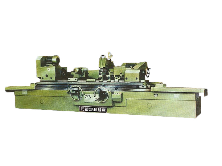
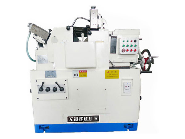
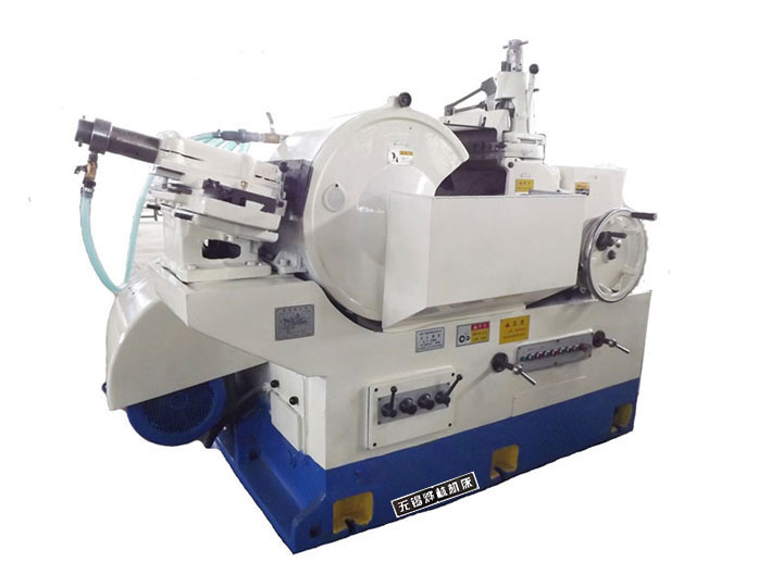
- Machine Base: High-rigidity cast iron or epoxy granite structure with advanced vibration-damping design, minimizing external vibrations and ensuring stable machining accuracy during radial plunge feed.
- Grinding Head: Equipped with CBN, diamond, or corundum grinding wheels (width ≥ workpiece grinding length), matched with a high-precision radial feed mechanism to achieve micrometer-level precision adjustment through CNC or mechanical transmission.
- Spindle System: High-rigidity spindle with non-contact hydrostatic bearing (runout ≤ 0.001 mm), driven by a servo motor to drive the workpiece to rotate stably at adjustable speeds, coordinating with the grinding wheel’s plunge feed.
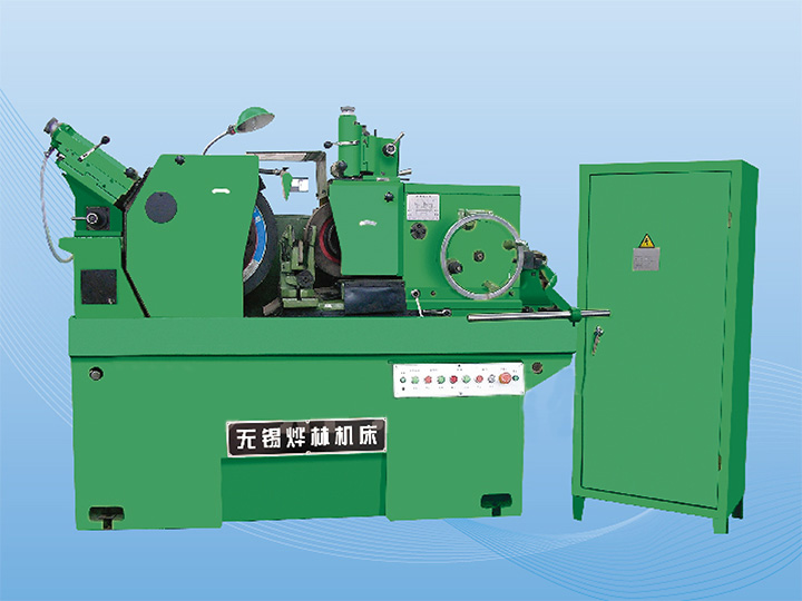
- Clamping & Positioning Mechanism: Composed of headstock, tailstock, and optional steady rests—headstock drives the workpiece rotation, tailstock supports the workpiece end, and steady rests prevent deflection of flexible or long workpieces during grinding.
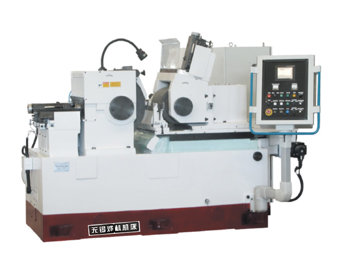
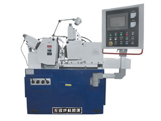
- Control & Cooling System: Advanced CNC control system (Siemens Sinumerik, Fanuc) for precise feed control, plus a high-pressure cooling system to reduce grinding heat, flush debris, and avoid workpiece burns caused by concentrated heat.
2.2 Working Principle
The workpiece is firmly clamped between the headstock and tailstock, rotating continuously at a set speed. The grinding wheel rotates at high speed (1000–6000 rpm) and feeds radially into the workpiece at a slow, steady rate (0.1–5 mm/min), gradually removing the surface allowance until the required size and precision are achieved. Unlike traverse grinding, there is no axial movement between the grinding wheel and the workpiece, and the grinding wheel width is usually greater than the workpiece’s grinding length, allowing one-time or multi-time plunge grinding to complete the processing, which significantly reduces idle stroke time and improves efficiency. The entire process relies on precise radial feed control to ensure uniform material removal and stable surface quality.
3. Classification and Key Characteristics
3.1 Classification
- By Structure: Horizontal (mainstream, for small to medium-sized short shafts) and vertical (for large heavy workpieces), with multi-spindle models available for simultaneous processing of multiple workpieces to improve production efficiency.
- By Control: Manual (small-batch repair), semi-automatic, and full-CNC (mainstream for mass production), with CNC models supporting automatic parameter adjustment, in-process monitoring, and integration with loading/unloading systems.
- By Processing Type: Straight plunge grinding (radial feed perpendicular to the workpiece axis) and angular plunge grinding (grinding wheel inclined, enabling simultaneous grinding of diameters and flat surfaces in one plunge).
3.2 Core Characteristics
- High Efficiency: Radial plunge feed eliminates axial movement, reducing idle time; suitable for mass production, with processing efficiency 30%–50% higher than traverse
cylindrical grinders.
- Stable Precision: Achieves roundness ≤ 0.8 μm, surface roughness Ra 0.32–0.63 μm, and dimensional accuracy ±0.001 mm, meeting the precision requirements of short cylindrical parts.
- Strong Adaptability: Compatible with various materials (alloy steel, cast iron, ceramics) and short cylindrical workpieces (max diameter up to 700 mm, max length less than grinding wheel width), especially suitable for stepped shafts and parts with shoulders.
- Simplified Operation: CNC models support automatic programming and feed control, reducing manual intervention; modular design enables quick tooling change for different workpieces.
4. Key Parameters and Selection
4.1 Core Parameters
Core parameters include processing capacity (max workpiece diameter φ5–φ700 mm, max length 50–620 mm, max weight 10–5000 kg), grinding precision (roundness ≤ 0.8 μm, Ra 0.32–0.63 μm), spindle speed (1000–6000 rpm), radial feed rate (0.1–5 mm/min), and grinding wheel specifications (diameter up to 760 mm).
4.2 Selection Principles
Select structure based on workpiece size (horizontal for small parts, vertical for large heavy workpieces), control mode by production scale (CNC for mass production), and grinding wheel material by workpiece hardness (CBN for hardened steel, corundum for general materials). For flexible or long workpieces, choose models with steady rests to prevent deflection; for complex contours, opt for angular plunge grinding models.
5. Industrial Applications
Widely used in automotive manufacturing (piston pins, crankshaft journals, transmission shafts), bearing industry (bearing rings, cylindrical rollers), precision machinery (pins, small shafts), and hydraulic industry (hydraulic cylinder rods). They are particularly suitable for mass production of short cylindrical parts and stepped shafts, and can also be used for grinding delicate seal grooves that are prone to deformation during turning.
6. Operation and Troubleshooting
6.1 Operation Tips
- Adjust spindle speed and radial feed rate according to workpiece material and hardness; use lower feed rate for precision finishing to avoid workpiece burns.
- Calibrate clamping and positioning accuracy before operation; use steady rests for flexible workpieces to minimize deflection and ensure processing precision.
- Regularly dress and balance the grinding wheel to prevent clogging and uneven wear; maintain the cooling system to ensure sufficient coolant supply and avoid debris accumulation.
6.2 Common Troubleshooting
Common faults and solutions: Workpiece burns are caused by excessive feed rate or insufficient cooling, resolved by reducing feed rate and checking the cooling system; poor roundness results from spindle runout or workpiece deflection, fixed by calibrating the spindle and using steady rests; surface scratches are caused by grinding wheel passivation or debris, solved by dressing/replacing the grinding wheel and filtering coolant.
7. Development Trends
Developing towards intelligence (AI-based real-time parameter optimization and chatter monitoring), automation (unmanned production with automatic loading/unloading robots), higher precision (roundness ≤ 0.5 μm), and multi-functional integration (combining plunge grinding with deburring and measurement to realize closed-loop machining). Additionally, improvements in rigidity and dynamic stability enable them to handle larger stock removal, replacing rough turning and finish grinding in some applications.
8. Conclusion
As specialized precision equipment for external cylindrical grinding, plunge cylindrical grinders stand out for their high efficiency and stable precision, making them irreplaceable in mass production of short cylindrical parts. Their unique radial plunge feed mode and simple structure meet the technical needs of automotive, bearing, and precision machinery industries, providing reliable support for efficient and high-precision manufacturing.
 English