Grinding a long plain cylindrical shaft—defined as a straight, cylindrical workpiece with a length-to-diameter ratio (L/D) ≥ 10 (e.g., 1-meter-long shafts with 100 mm diameter)—requires a machine capable of maintaining precision across the entire shaft length while minimizing vibration-induced errors. The primary tool for this task is a cylindrical grinding machine, specifically configured to handle long workpieces via specialized support systems and precise motion control. Unlike universal grinders (which prioritize versatility) or surface grinders (which focus on flat surfaces), cylindrical grinders are engineered for rotational symmetry, ensuring uniform material removal, tight dimensional tolerances (typically ±0.001–0.01 mm), and smooth surface finishes (Ra 0.2–1.6 μm) critical for shaft functionality (e.g., bearing fits, torque transmission). This article details the types of cylindrical grinding machines suitable for long plain shafts, their design adaptations, grinding processes, and selection criteria—aligned with ISO 8688 (grinding process standards) and ANSI B5.45 (machine tool accuracy).
1. Key Cylindrical Grinding Machine Types for Long Plain
Cylindrical Shafts
Not all cylindrical grinders are equally suited for long shafts. The two most effective configurations are plain cylindrical grinders (for simple external grinding) and CNC cylindrical grinders (for high-precision, automated processing), each with design features tailored to address the unique challenges of long workpieces (e.g., deflection, vibration).
| Machine Type | Design Adaptations for Long Shafts | Ideal Shaft Specifications |
|-----------------------------|---------------------------------------------------------------------------------------------------|-------------------------------------------------------------------------------------------|
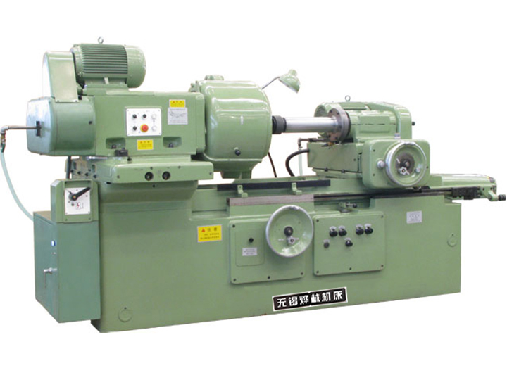
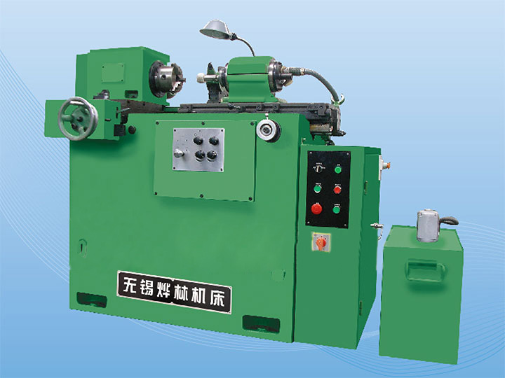
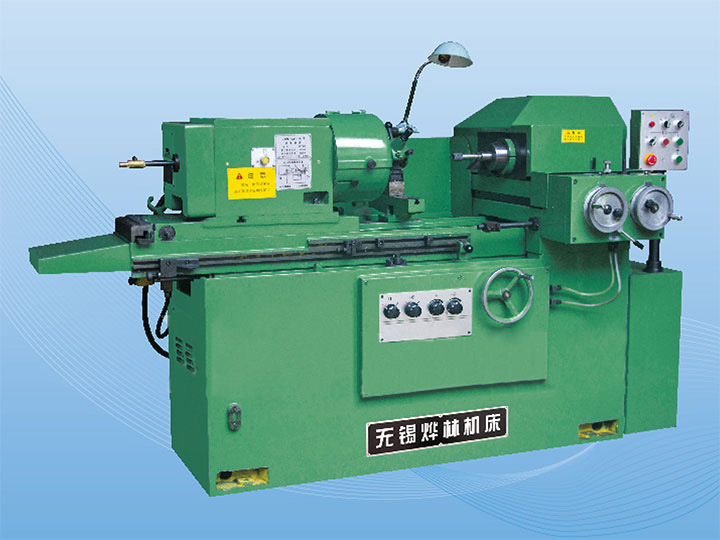
| Plain Cylindrical Grinder (Manual/Semi-Automatic) | - Multiple Work Centers: Two or three adjustable "dead centers" (tailstocks) to support the shaft at intervals, preventing deflection under grinding forces. <br> - Extended Worktable: A long, rigid table (length ≥ 1.2x shaft length) to accommodate the full workpiece. <br> - Low-Vibration Frame: Heavy-duty cast-iron construction with vibration-dampening ribs to minimize chatter (surface irregularities caused by vibration). | Shafts with L/D = 10–20 (e.g., 800 mm length × 80 mm diameter); low-to-medium production volumes (10–100 shafts/batch); simple straight profiles (no grooves or tapers). |
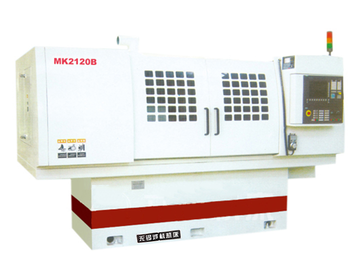
| CNC Cylindrical Grinder | - Servo-Controlled Work Centers: Motorized, programmable dead centers that adjust dynamically to shaft deflection (via load sensors) during grinding. <br> - C-axis Rotation: Precise control of workpiece rotational speed (synchronized with wheel feed) to ensure uniform material removal. <br> - In-Process Measurement: Integrated laser or touch probes that continuously monitor shaft diameter and straightness, auto-correcting feed rates to maintain tolerances. <br> - Extended Wheelhead Travel: A wheelhead (holds the grinding wheel) with linear travel ≥ shaft length, ensuring consistent grinding pressure across the entire workpiece. | Shafts with L/D ≥ 20 (e.g., 1.5 m length × 75 mm diameter); high-precision requirements (±0.001 mm); high-volume production (100+ shafts/batch); or shafts requiring tight straightness (≤0.05 mm/m). |
| Specialized Long-Shaft Cylindrical Grinder | - Bed-Type Design: A fixed, ultra-rigid bed (instead of a moving table) with the wheelhead traveling along the shaft—reduces table deflection for extremely long shafts. <br> - Hydrostatic Bearings: Fluid-lubricated bearings for the workhead and wheelhead, eliminating mechanical friction and ensuring smooth motion (critical for shafts with L/D > 30). <br> - Coolant Delivery Systems: High-pressure coolant nozzles positioned along the shaft length to dissipate heat (prevents thermal expansion, which distorts long shafts). | Ultra-long shafts (L ≥ 2 m, L/D > 30); aerospace or power generation components (e.g., turbine shafts, drive shafts); shafts requiring near-micron tolerances (±0.0005 mm). |
2. Why Cylindrical Grinders Excel at Long Plain Shafts
Long plain cylindrical shafts present unique grinding challenges—primarily shaft deflection (bending under grinding pressure) and dimensional inconsistency (varying diameter along the shaft length). Cylindrical grinders address these via three critical design principles:
2.1 Multi-Point Workpiece Support
Long shafts (L/D ≥ 10) act like cantilevers if only supported at both ends—grinding pressure (typically 5–20 N) causes mid-span deflection, leading to tapering (larger diameter at ends, smaller in the middle). Cylindrical grinders solve this with:
- Dead Centers: Stationary or motorized centers that support the shaft at 300–500 mm intervals (e.g., a 1.2 m shaft uses three centers: one at each end, one at the midpoint).
- Steady Rests: Adjustable frictionless supports (often with roller bearings) that cradle the shaft without impeding rotation—used for shafts with L/D > 20 to further reduce deflection.
2.2 Precision Motion Control
Uniform material removal across a long shaft requires synchronized movement of the grinding wheel and workpiece:
- Wheel Feed: The grinding wheel moves linearly along the shaft at a constant feed rate (0.01–0.1 mm/rev), ensuring each section of the shaft receives the same amount of material removal.
- Workpiece Rotation: The shaft rotates at a speed proportional to its diameter (typically 10–50 m/min surface speed) to avoid uneven wear on the grinding wheel and ensure a consistent finish.
2.3 Vibration Dampening
Vibration (from unbalanced shafts, wheel imbalance, or machine resonance) causes "chatter"—wavy surface patterns that render the shaft unusable for precision applications (e.g., bearing fits). Cylindrical grinders mitigate this with:
- Heavy Cast-Iron Frames: Dense cast iron absorbs vibration better than steel, reducing amplitude by 50–70% compared to lighter machines.
- Balanced Grinding Wheels: Wheels are dynamically balanced (per ISO 1940) to minimize centrifugal force-induced vibration at high speeds (3,000–6,000 RPM).
3. Step-by-Step Grinding Process for Long Plain Cylindrical Shafts
The process for grinding long plain shafts is standardized to ensure precision and consistency, regardless of machine type (manual or CNC):
Step 1: Workpiece Preparation & Mounting
1. Inspect the Shaft: Check for initial straightness (using a dial indicator) and remove any surface defects (e.g., rust, burrs) with a wire brush or deburring tool.
2. Mount Centers: Secure the shaft between the headstock center (drives rotation) and tailstock centers (support). For long shafts, add intermediate dead centers or steady rests at mid-span.
3. Align the Shaft: Use a dial indicator to align the shaft’s axis with the machine’s grinding axis—misalignment >0.01 mm/m causes taper in the final product.
Step 2: Grinding Wheel Selection & Preparation
1. Choose the Wheel: Select an abrasive wheel based on the shaft material:
- Steel Shafts: Aluminum oxide (Al₂O₃) wheels (grain size 60–120) for general grinding; cubic boron nitride (CBN) wheels (grain size 80–150) for high-hardness steel (HRC > 50).
- Stainless Steel/Alloy Shafts: Silicon carbide (SiC) wheels (grain size 80–120) to avoid material loading (metal buildup on wheel).
2. Dress the Wheel: Use a diamond dresser to true the wheel (restore its circular shape) and dress its surface (expose fresh abrasive grains)—critical for consistent material removal.
Step 3: Grinding Operation
1. Rough Grinding: Remove excess material (0.1–0.5 mm) at a high feed rate (0.1–0.2 mm/rev) and low wheel speed (3,000 RPM). This step shapes the shaft to near-final dimensions while minimizing heat generation.
2. Finish Grinding: Reduce feed rate (0.01–0.05 mm/rev) and increase wheel speed (4,500–6,000 RPM) to achieve the target tolerance (±0.001–0.01 mm) and surface finish (Ra 0.2–1.6 μm). For CNC machines, in-process probes adjust feed rates automatically if deviations are detected.
3. Coolant Application: Apply high-pressure coolant (10–20 bar) continuously during grinding to:
- Dissipate heat (prevents thermal expansion of the shaft, which distorts dimensions).
- Flush away abrasive swarf (prevents re-deposition on the shaft surface).
Step 4: Post-Grinding Inspection & Finishing
1. Dimensional Check: Measure diameter at 3–5 points along the shaft length (using a micrometer) to verify uniformity. Check straightness with a dial indicator (maximum allowable deviation: 0.05 mm/m for industrial shafts, 0.01 mm/m for precision shafts).
2. Surface Finish Test: Use a profilometer to measure Ra (arithmetic mean roughness) and ensure it meets specifications (e.g., Ra 0.4 μm for bearing journals).
3. Deburring: Remove any residual burrs from the shaft ends with a fine file or abrasive pad—burrs cause bearing damage during assembly.
4. Selection Criteria for Grinding Long Plain Cylindrical Shafts
To choose the right cylindrical grinder, evaluate these factors based on your shaft specifications and production needs:
4.1 Shaft Dimensions (Length, Diameter, L/D Ratio)
- Length: Select a machine with a worktable or wheelhead travel ≥ 1.2x the shaft length (e.g., a 1.5 m shaft requires a machine with 1.8 m travel).
- L/D Ratio: For L/D = 10–20: Plain cylindrical grinder with 2–3 dead centers. For L/D > 20: CNC cylindrical grinder with servo-controlled steady rests. For L/D > 30: Specialized bed-type long-shaft grinder with hydrostatic bearings.
4.2 Precision Requirements
- Tolerance: ±0.01 mm (industrial shafts) → Manual plain cylindrical grinder. ±0.001 mm (precision shafts, e.g., aerospace components) → CNC cylindrical grinder with in-process measurement.
- Straightness: ≤0.05 mm/m → Standard supports. ≤0.01 mm/m → CNC machine with dynamic center adjustment.
4.3 Production Volume & Automation Needs
- Low Volume (<10 shafts/batch): Manual plain cylindrical grinder (lower cost, flexible setup).
- Medium Volume (10–100 shafts/batch): Semi-automatic cylindrical grinder (manual setup, automated grinding cycle).
- High Volume (>100 shafts/batch): CNC cylindrical grinder (fully automated setup, in-process inspection, and data logging for quality control).
4.4 Shaft Material
- Soft Materials (Aluminum, Brass): Prioritize a machine with low-vibration controls (to avoid surface chatter) and aluminum oxide wheels.
- Hard Materials (Tool Steel, Titanium): Choose a grinder with a high-torque spindle (to drive CBN wheels) and coolant systems for heat management.
5. Common Mistakes to Avoid
- Insufficient Support: Using only two end centers for shafts with L/D > 15—causes mid-span deflection and taper.
- Overlooking Wheel Balancing: Unbalanced wheels create vibration and chatter, ruining surface finish.
- Ignoring Thermal Expansion: Grinding without coolant or grinding too quickly generates heat, causing the shaft to expand and leading to undersized dimensions once cooled.
 English